The LEGO Grand Piano 21323 is a great model, full of clever details and impressive engineering.
It contains a bit of electronics, that allow it to talk with a phone app via Bluetooth.
The app can play a few built-in tunes while running the motor inside the piano, which pulls some keys down in a regular pattern, so you can pretend to have a "player piano". The app can also wait for you to press any key on the piano (they all move a little flag in front of the optical sensor) before playing the next note, so you can pretend to be playing.
That's fun, but not really enough: there are 25 independent keys, surely we can make them play the right note!
After some research, I decided to use optical sensors and a big microcontroller. How hard can it be? ☺
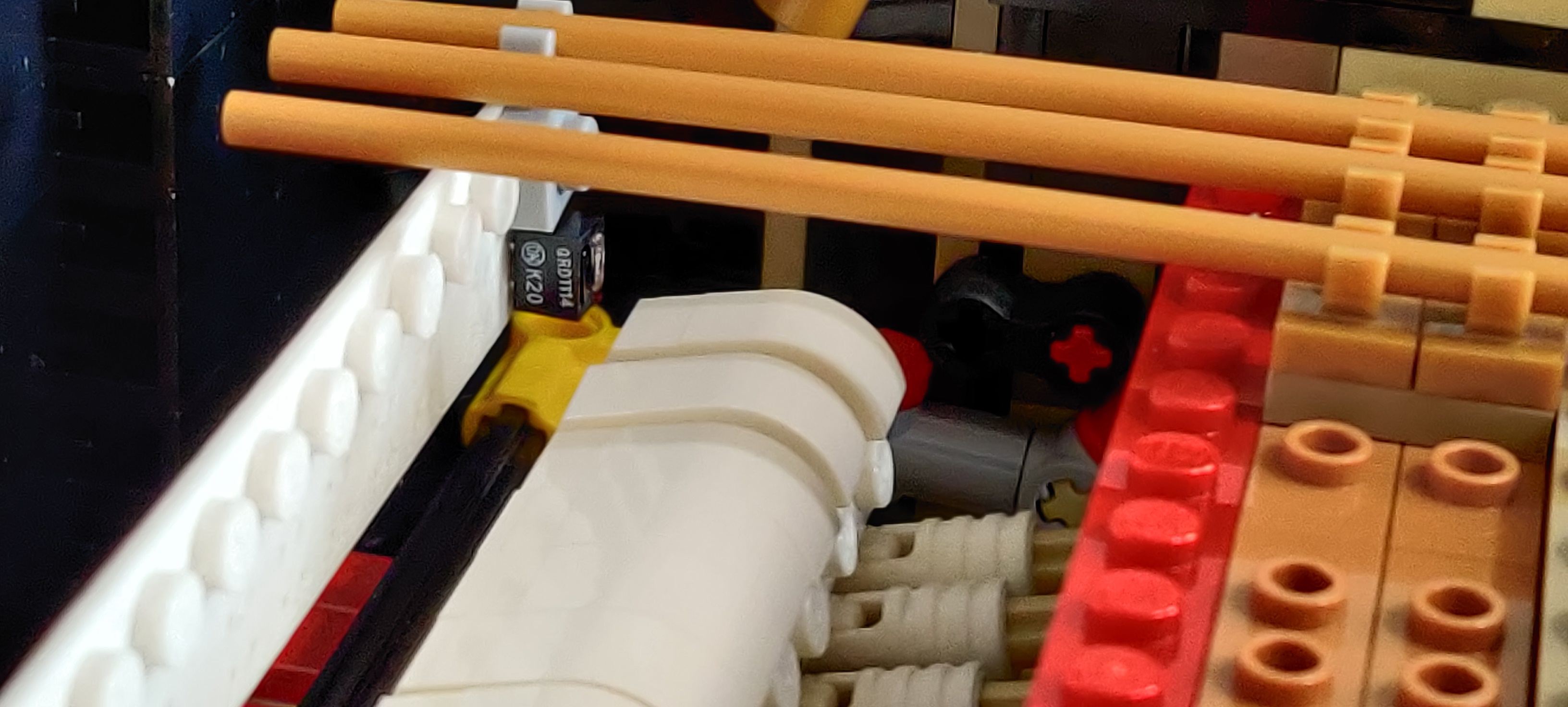
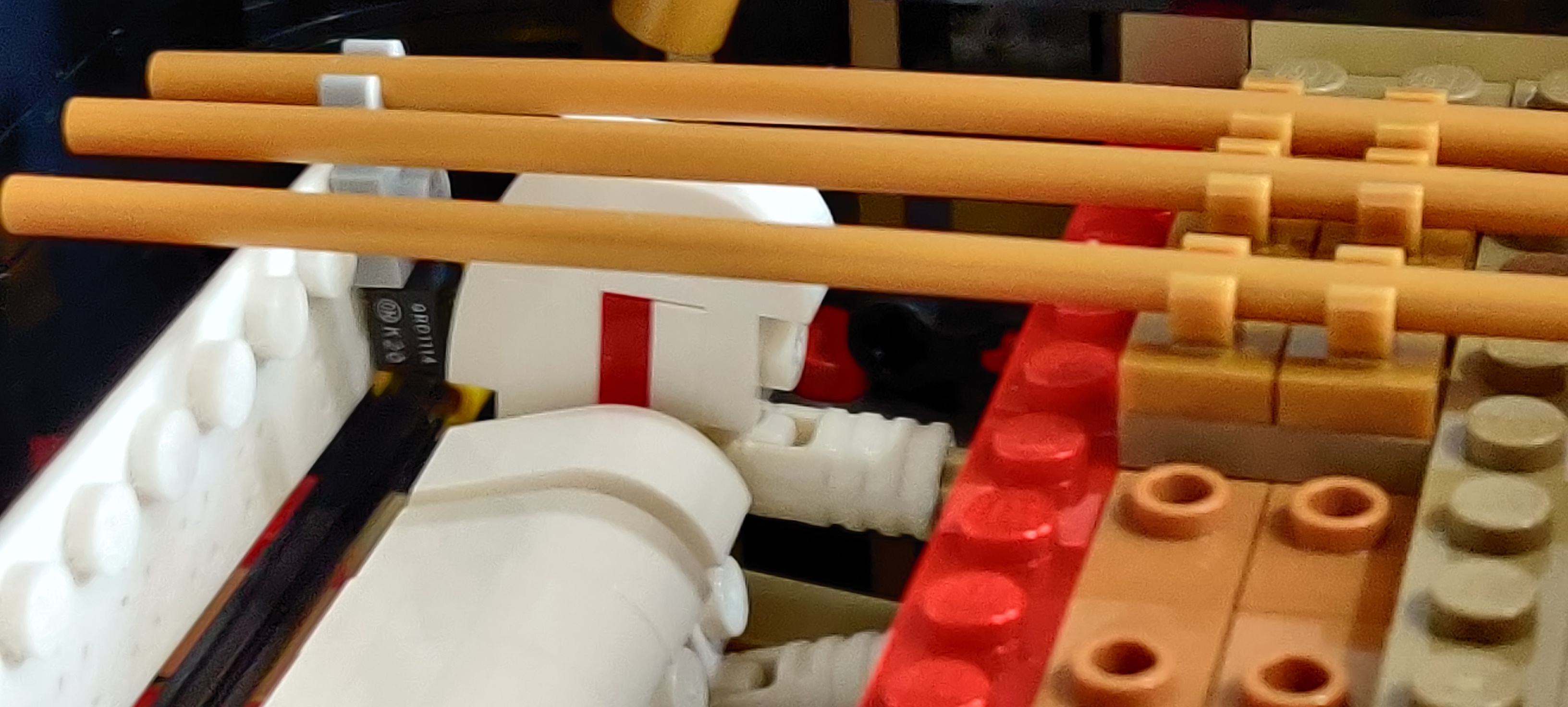
As sensor I picked the QRD1114, which is dead easy to use: infrared LED plus phototransistor, with a very narrow and short area of sensitivity, so there's very little chance of nearby keys setting off the wrong sensor.
The controller I used is a Lilygo TTGO-T7 v1.3, just because I had bought a bunch of them. It's a very small ESP32 board, with 40 pins broken out, and support for charging a lithium battery from USB.
Note
The v1.3 is a d1_mini32 board as far as the esp32-arduino libraries are concerned, v1.4 is a esp32wrover. There are probably other variants, so you may need to adjust something if you want to replicate my build
First step was figuring out how to connect the sensors to the controller. The LED in the QRD1114 can easily work with about 20mA, so I can drive one directly from the ESP32, whose GPIO pins can drive up to about 30mA. 25 sensors fit nicely in a 5×5 matrix, so something like this should work:

Pulling a "row" pin high (with the others low) and a "col" pin low (with the others in high-impedance / tristate), we can turn on one sensor at a time, so we can scan the matrix. When the phototransistor sense light reflecting from an object in front of it, it will pull down the "sense" pin, which we can read via the ADC in the controller.
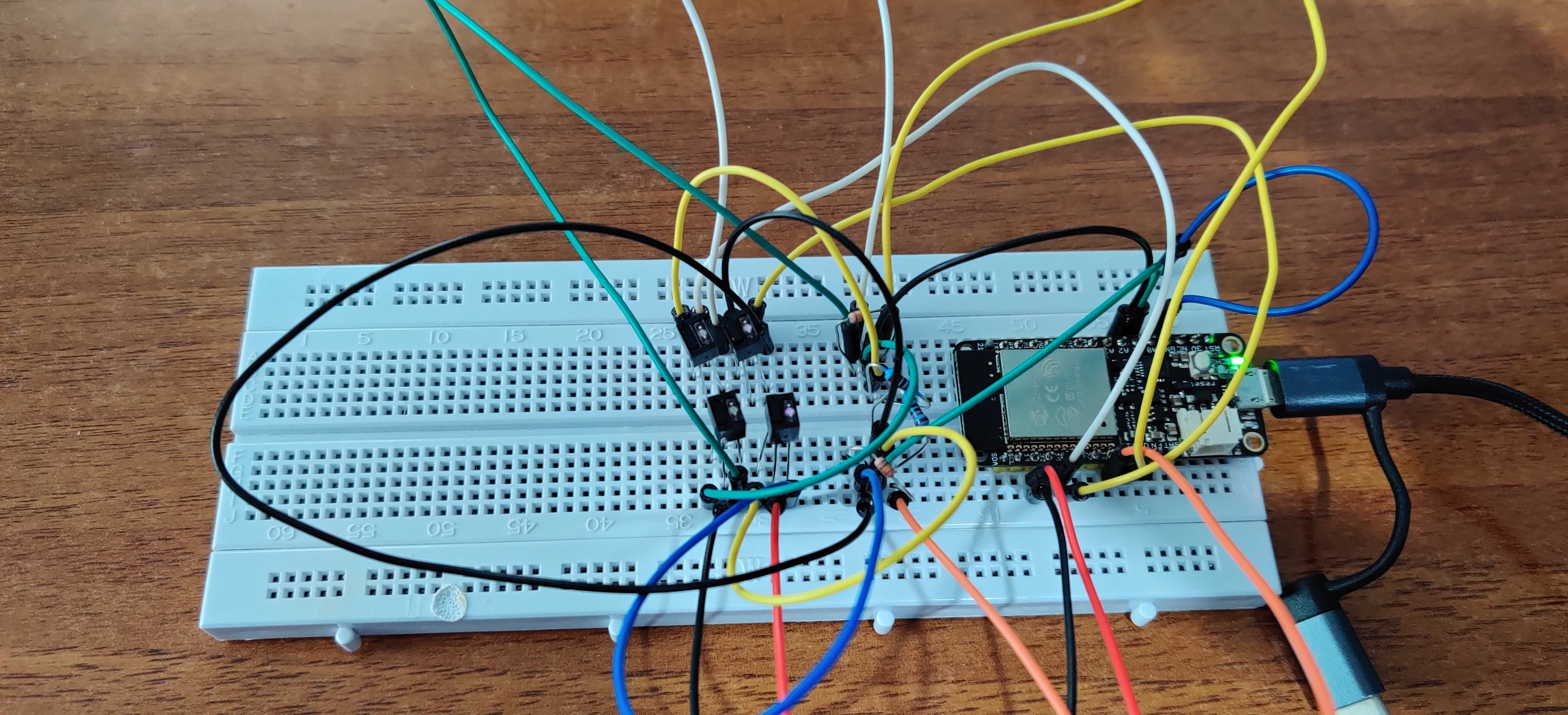
Testing that design on a breadboard proved that it can work!
How are we going to keep the sensors in the right place inside the piano, though? We're going to print a support that's compatible with Lego pieces!
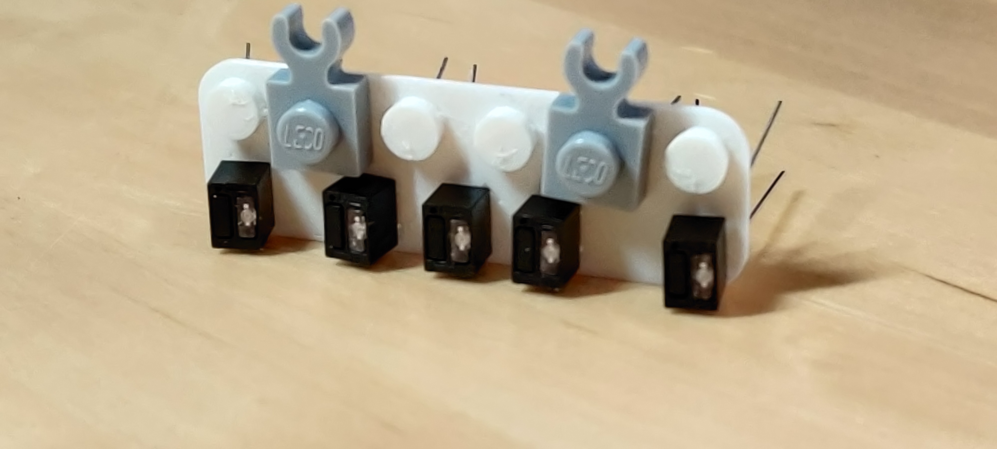
My printer (a Prusa i3 MK3S) can print holes of the right size for standard vias, and can print the whole sensor support in one go (29 studs long). The sensors need to be aligned with the hammers (there's no space behind the stems of the keys, also the hammers are white so more visible to the phototransistor, and move more, so it's less probable we'll have false positives). I used OpenSCAD to model the support.
We also must check positioning on the other two axes, of course.
At this point someone must be asking: how are we going to solder those sensors on a plastic board? And the answer is, we're not going to! I decided to go with wire-wrapping!
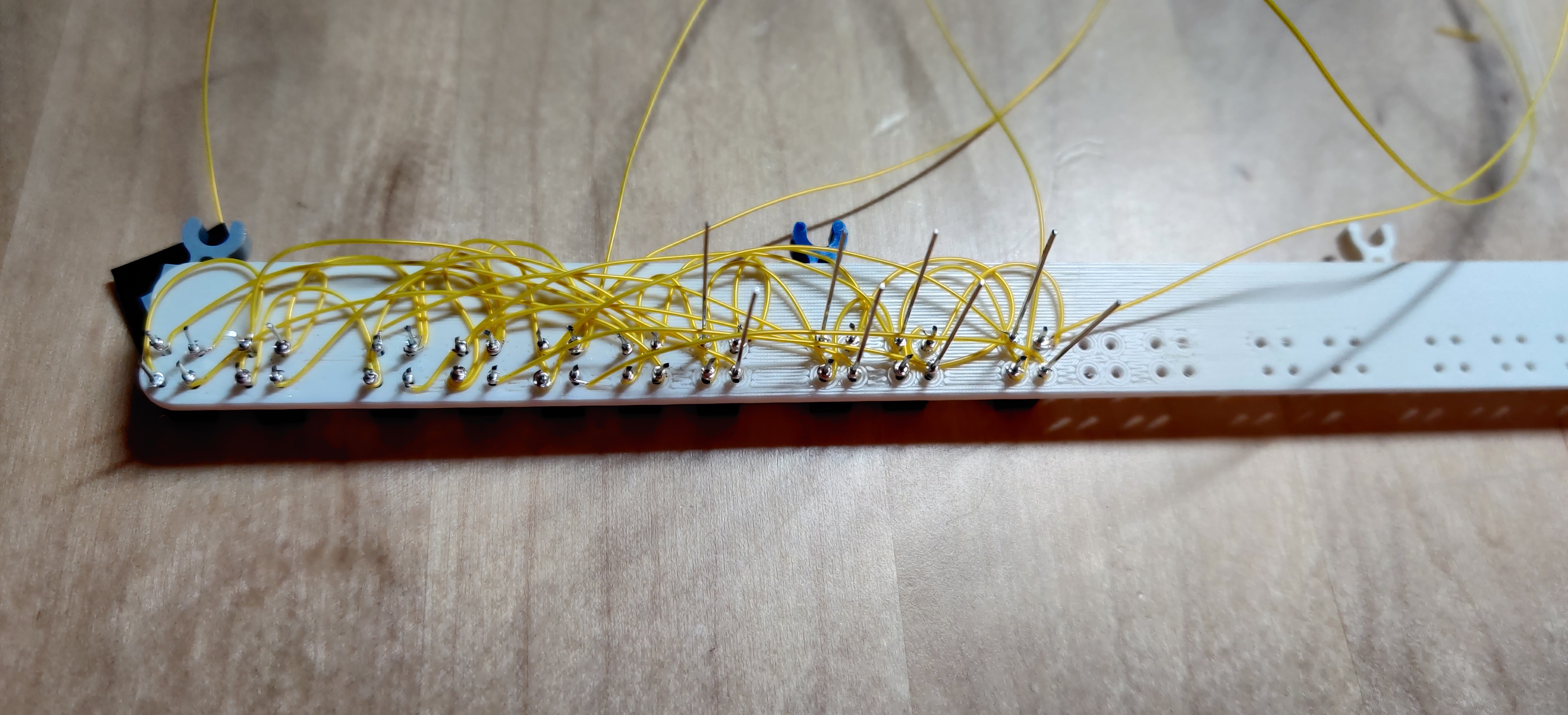
The sensors have 4 pins, numbered counter-clockwise looking at the LED / phototransistor faces:
- phototransistor collector, to connect to pull-up resistor and to "row" pin
- phototransistor emitter, to connect to "column" pin
- LED anode, to connect to current-limiter resistor and to "row" pin
- LED cathode, to connect to "column" pin
so the whole wiring looks like this:
aM aN aO aP aQ cM cN cO cP cQ
14 14 14 14 14 14 14 14 14 14 …
23 23 23 23 23 23 23 23 23 23 …
Mb Nb Ob Pb Qb Md Nd Od Pd Qd
where a, c go to the pull-up resistors; b, d go to the limiter resistors, and M, N, O, P, Q go to the column pins.
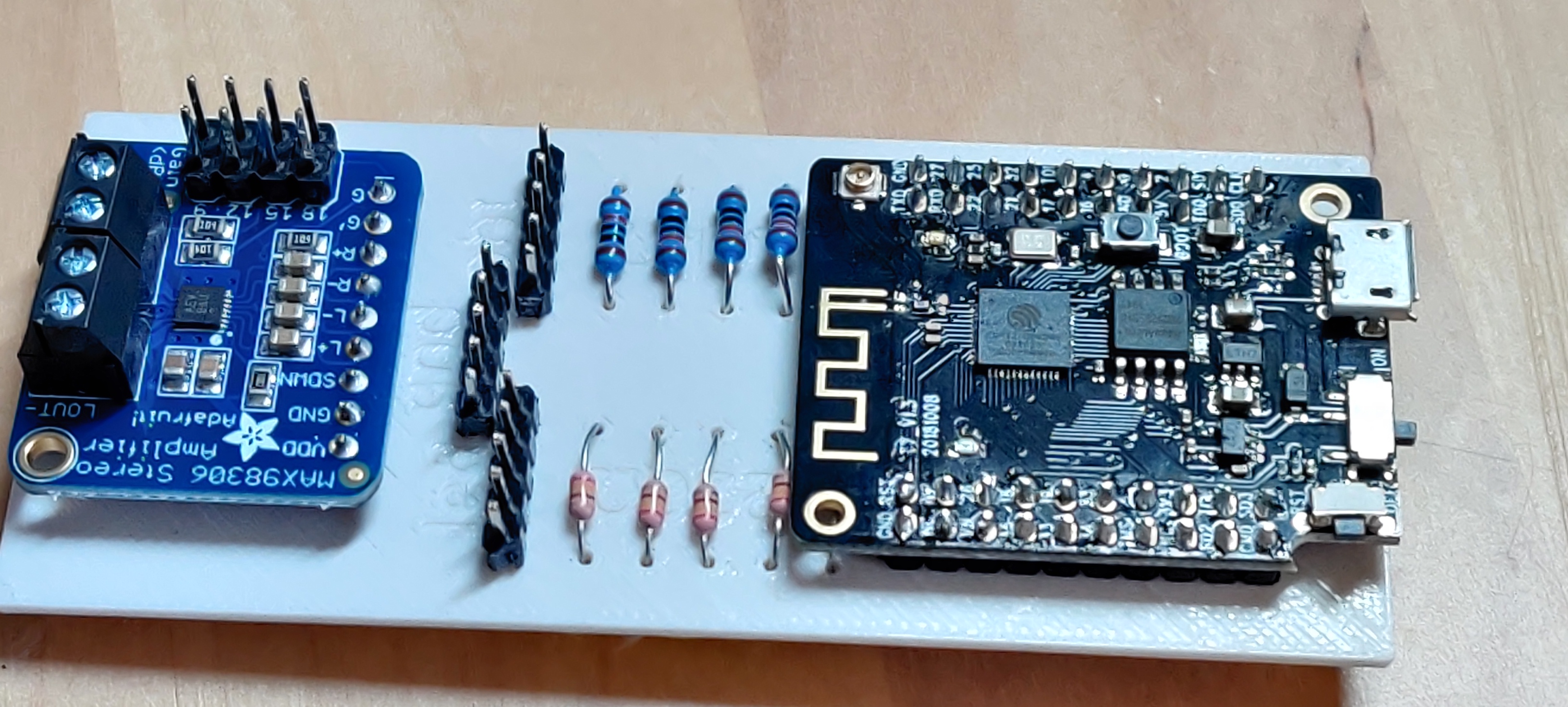
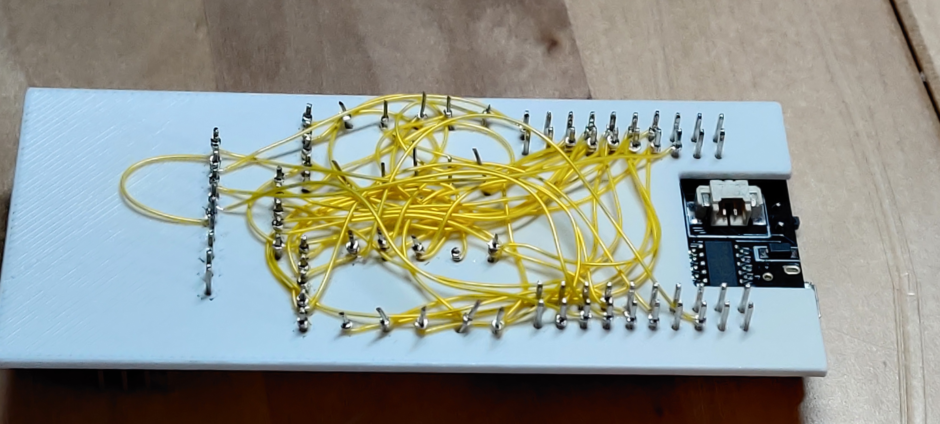
The controller board is built in a similar way: 3D-printed and wire-wrapped (see the model).
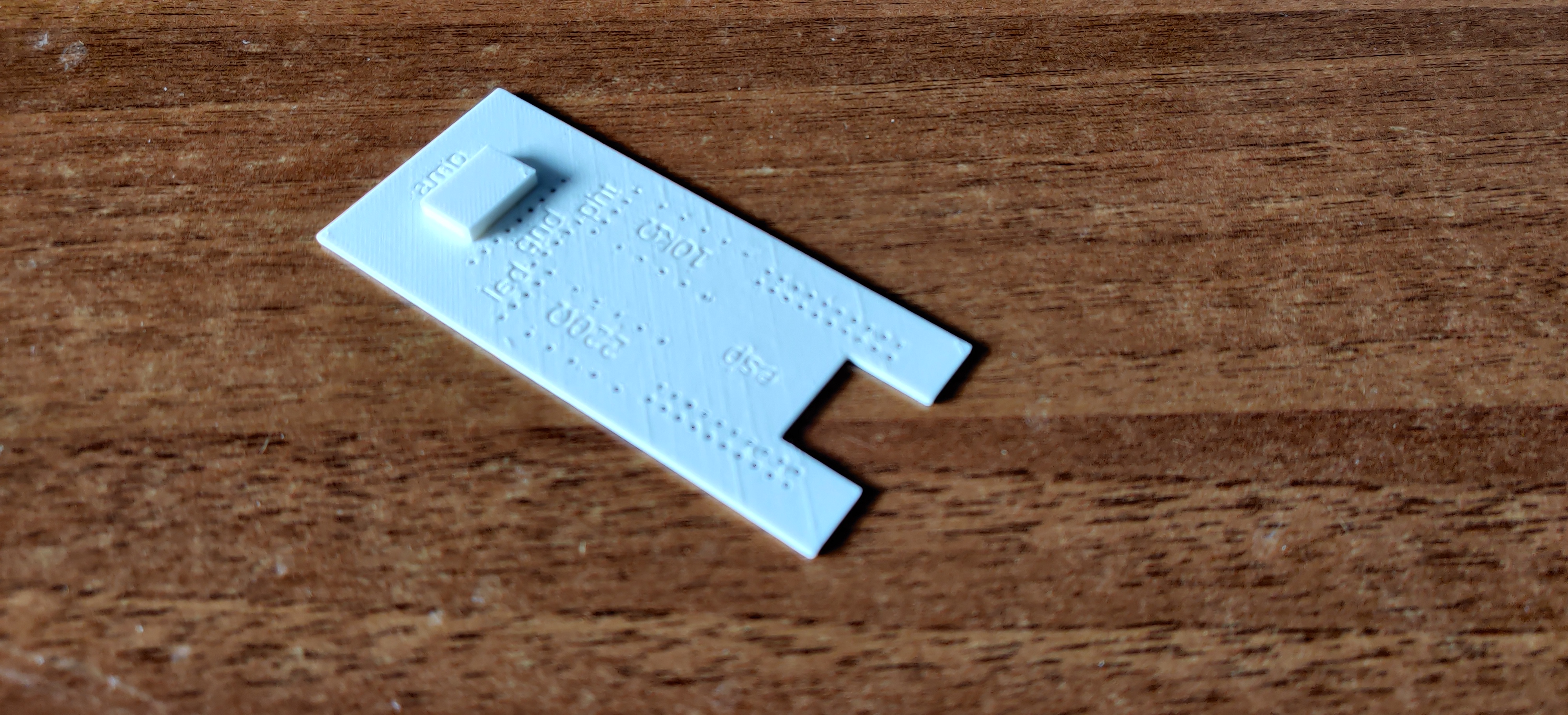
The notch in the board corresponds to the battery connector, and the raised block is to hold up the small AdaFruit audio amplifier
I had some problems with the row / column connections, because not all the GPIO pins can actually be used. After some trial and error, I settled on:
- row pins: 05 23 19 18 26
- colums pins: 17 33 16 21 22
- ADC pins: 02 04 12 27 14
- DAC pin: 25
- amp enable: 32
The program was a bit fiddly to get right, but not particularly complicated, you can see it in my Git repository.
Note
The TTGO board gave me some problems with uploading the compiled image, with errors like A fatal error occurred: Timed out waiting for packet content or Invalid head of packet (0xE0). To fix those, I had to set the upload speed by hand in the Makefile.
First test with a few sensors on a breadboard:
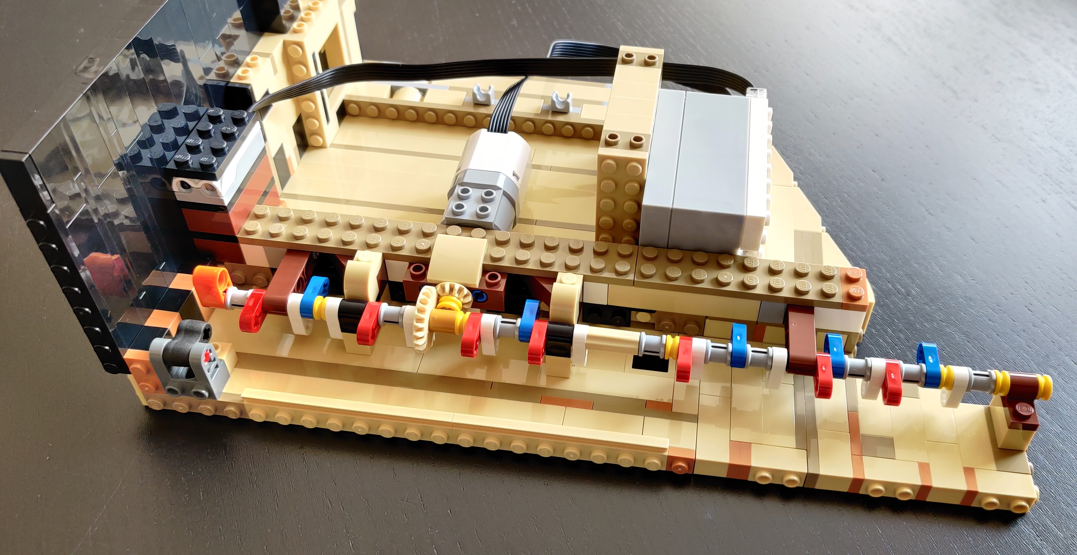
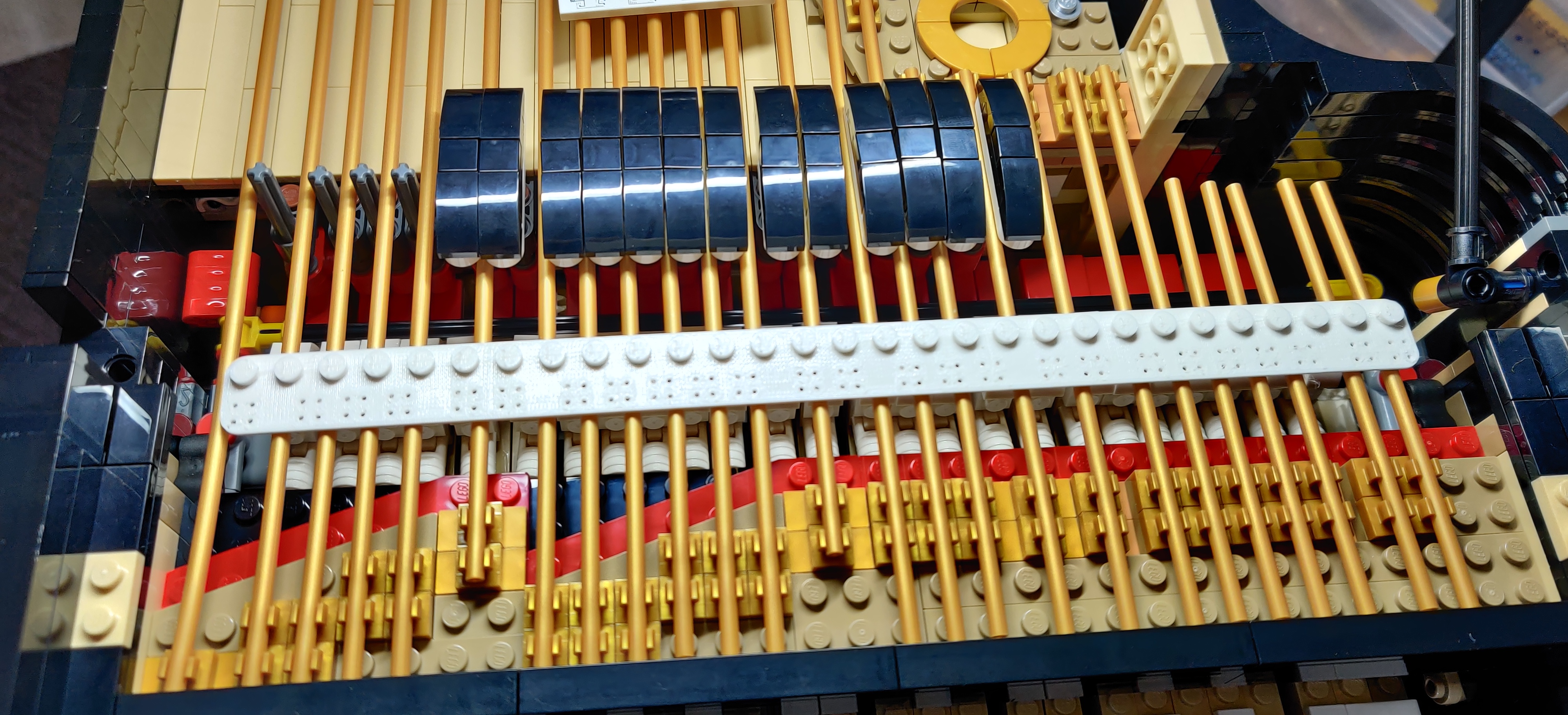
and with all the sensors, mounted inside the piano:
I removed the Lego electronics to make space for the wires and the controller board.
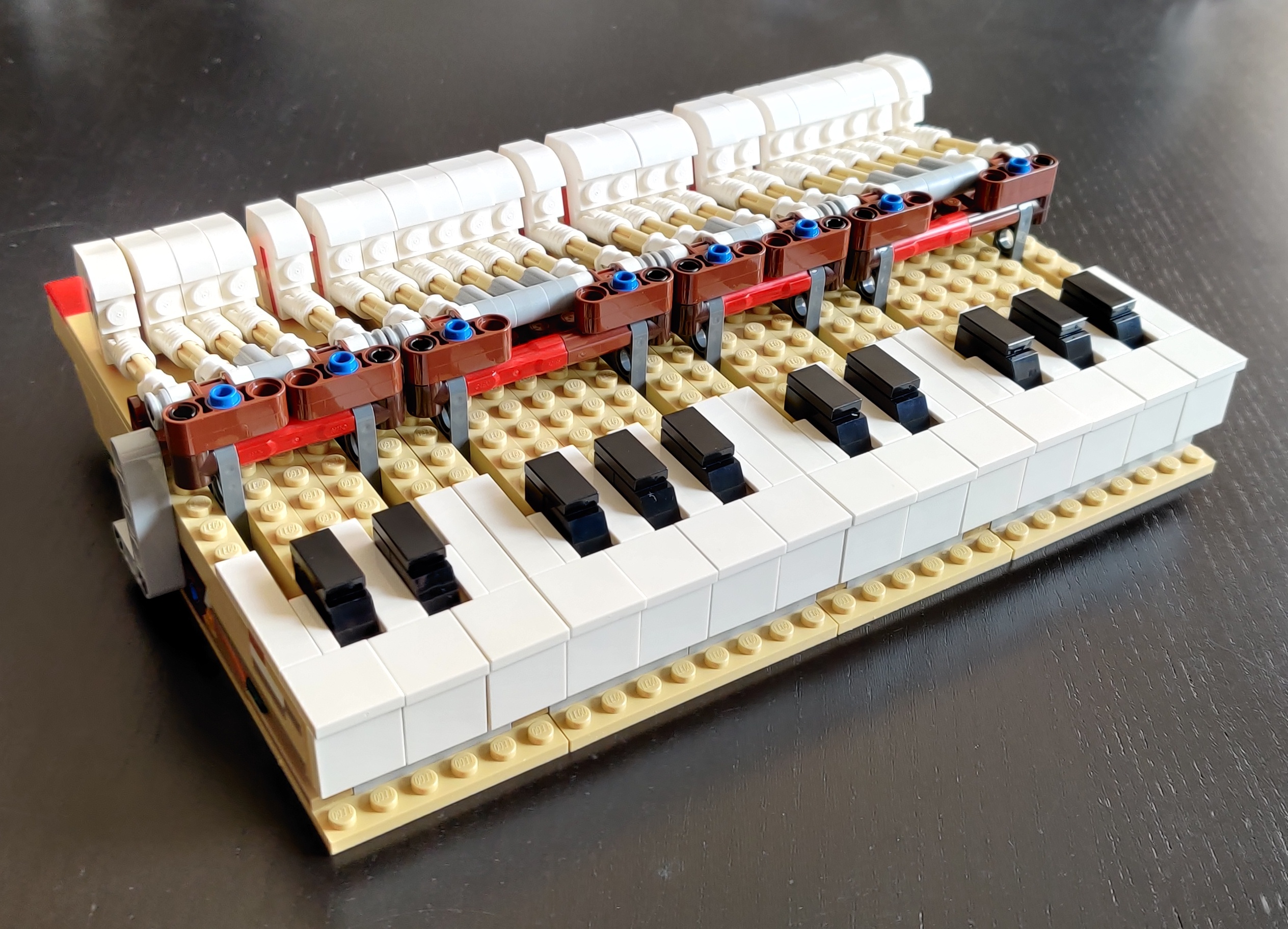
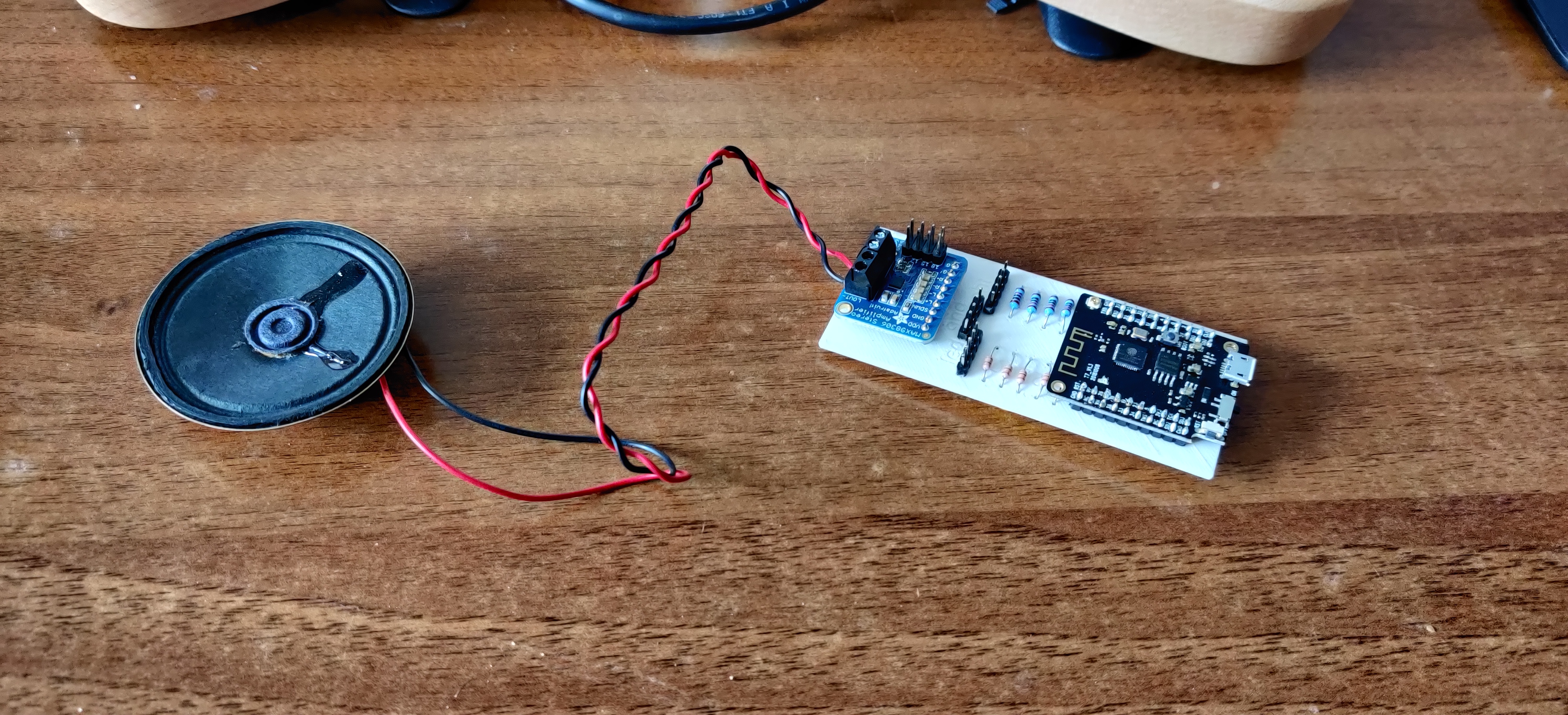
And, finally, the whole assembled set:
That's great, but it sounds nothing like a piano. It took about two days of experimentation, but I finally managed to get the ESP32 to use a soundfont, via the TinySoundFount library (actually the ESP-optimised version):


